

 Technical Information Power And Control Cables Power Appendixes Guide to the Wiring Regulations General requirements of earthing and bonding
 صفحه General requirements of earthing and bonding
| General requirements of earthing and bonding | |
|
The protective measures for general application are: * Automatic disconnection of supply; * Double or reinforced installation; * Electrical separation; * Extra-low voltage provided by SELV or PELV |
 |
| The protective measure ‘automatic disconnection of supply’ is by far the most common and makes specifc requirements for both protective earthing and protective bonding. | |
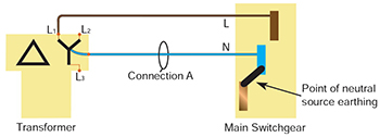
| A typical arrangement for an on-site transformer with the neutral earth link made in the main switchgear | |
| Again, we need to briefy review the requirements of the protective measure in order to establish earthing and bonding requirements. The basis of the measure is as follows. | |
|
* Basic protection (protection against direct contact) is protection from contact with live parts provided by basic insulation, or by barriers or enclosures. * Fault protection (protection against indirect contact) is provided by protective earthing, protective equipotential bonding and automatic disconnection in case of fault. In the event of a fault between a live conductor and an exposed-conductive- part of equipment, suffcient fault current fows to operate (trip or fuse) the overcurrent protection. For the protective measure to work, protective conductors are required to connect all exposed-conductive-parts (of equipment) to the earthing terminal. This is protective earthing and includes circuit protective conductors and the earthing conductor. To reduce shock voltages (touch voltages during a fault), and to provide protection in the event of an open circuit in the PEN conductor of a PME supply, protective equipotential bonding is also required. A simple installation with both circuit protective conductors and protective bonding conductors is shown in Following Figure : |
|
 |
|